The CHIP is a powerful $9 computer. I saw them online and ordered 5 of them some time ago as part of a potential home automation project, and because it’s always useful to have some small linux devices around with GPIO ability. I’ve recently been playing a lot with ESP8266 devices (more on this in some future blog posts), and I’ve been using the CHIP to program them via a breadboard and the serial port header connectors (exposed as ttyS0) and esptool.py. So far so good.
However, I want to put the CHIP devices into small boxes around the house and use something like find-lf for internal location tracking based on Wifi signals emitted from phones and other devices to figure out who’s in which room. Whilst the CHIP has 2 wifi devices (wlan0, wlan1) it doesn’t allow one to run in monitor mode while the other is connected to an AP. This means we need an extra Wifi card to be in monitor mode, and as I had a number of ESP8266’s lying around, I thought I’d write a small program to just print MAC and RSSI (signal strength) via the serial port.
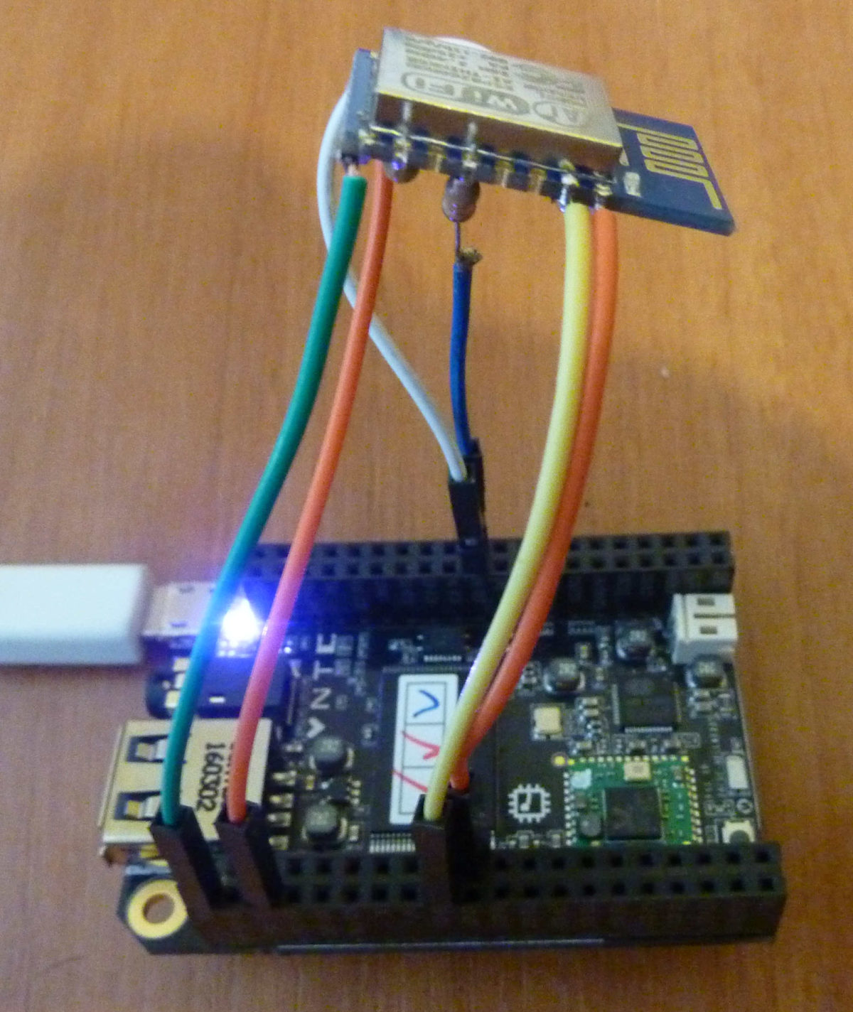
As these devices will be in sealed boxes I don’t want to have to go fiddling around with connectors on a breadboard to update the ESP8266 firmware, so I came up with a minimal design to allow reprogramming ESP8266 on-the-fly from CHIP devices (should work on anything with a few GPIO ports). Obviously the ESP8266 does have OTA update functionality, however as these devices will be in monitor mode I can’t use that. As the CHIP works at 3.3v, the same as ESP8266 chips this was pretty straight forwards involving 6 cables and 2 resistors, there were a few steps and gotchas to be aware of first though.

The main issue preventing this from working is that when the CHIP first boots up, the uBoot software listens for input for 2 seconds via ttyS0 (the serial port exposed on the header, not the USB one). When power first comes on, the ESP8266 will always output some bootloader messages via the serial port which means that the CHIP would never boot. Fortunately the processor has a number of different UARTs, a second one that is optionally exposed via the headers. You can read all about the technical details on this thread. In short, to expose the second serial port you need to download this dtb from dropbox and use it to replace /boot/sun5i-r8-chip.dtb. You then need to download this small program to enable the port and run it every boot up. This worked fine for me on the 4.4.13-ntc-mlc kernel. You can then use the pins found listed here to connect to the tx/rx of the ESP8266 serial and it won’t affect the boot-up of the CHIP.
The other nice thing about using ttyS2 rather than ttyS0 is that there are hardware flow control ports exposed (RTS, CTS) which I had hoped could be integrated into esptool to automatically handle the reset. Unfortunately it looks like esptool uses different hardware flow control ports to signal the ESP8266 bootloader mode/reboot so I had to connect these ports to GPIOs and trigger from there.
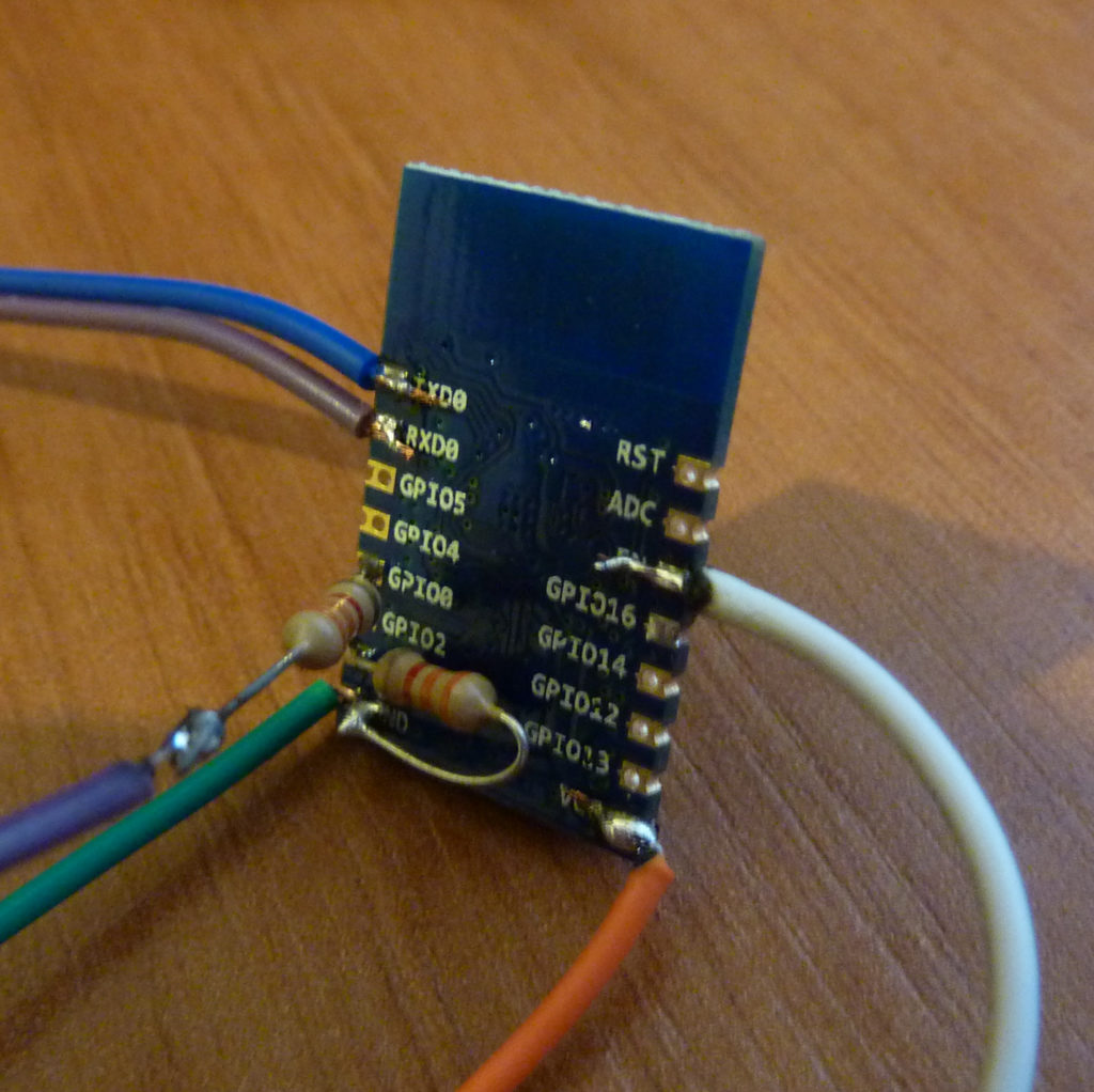
After doing this, wire the ESP8266 (I’m using the ESP-12 board, but should be the same for any other boards) to the CHIP in the following manner:
| ESP8266 pin |
CHIP connector |
| VCC |
3.3v |
| – |
Gnd |
| CH_PD / EN |
XIO-P6 |
| GPIO0 |
XIO-P7 via a resistor (eg 3.3k) |
| GPIO15 |
– via resistor (eg 3.3k) |
| TX |
LCD-D3 |
| RX |
LCD-D2 |
Note that on some ESP boards TX/RX are the wrong way round so if you don’t see anything try flipping the cables around.
I then wrote a small program (called restart_esp.py) to trigger different mode reboots of the ESP8266 from the CHIP:
import CHIP_IO.GPIO as GPIO
import time
import sys

pin_reset = "XIO-P6"
pin_gpio0 = "XIO-P7"

def start_bootloader():
        GPIO.output(pin_gpio0, GPIO.LOW)
        GPIO.output(pin_reset, GPIO.LOW)
        time.sleep(0.1)
        GPIO.output(pin_reset, GPIO.HIGH)

def start_normal():
        GPIO.output(pin_gpio0, GPIO.HIGH)
        GPIO.output(pin_reset, GPIO.LOW)
        time.sleep(0.1)
        GPIO.output(pin_reset, GPIO.HIGH)

GPIO.setup(pin_reset, GPIO.OUT)
GPIO.setup(pin_gpio0, GPIO.OUT)
if sys.argv[1] == 'bootloader':
        print("Bootloader")
        start_bootloader()
else:
        print("Normal start")
        start_normal()

GPIO.cleanup()
Then you can easily flash your ESP8266 from the CHIP using a command like:
python restart_esp.py bootloader; \
esptool.py -p /dev/ttyS2 write_flash --flash_mode dio 0 firmware.bin; \
python restart_esp.py normal